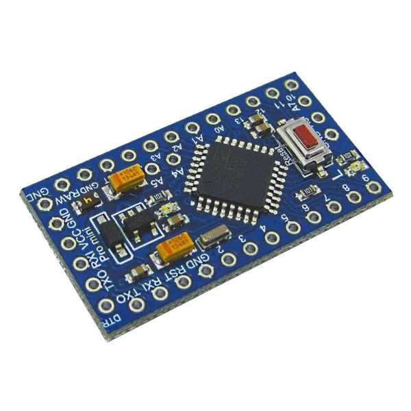
Arduino 端口扩展器
通过这个方案,您可以通过 ESPHome 控制远程 Arduino 开发板的引脚。Arduino 作为端口扩展器,允许您使用比标准 ESP8266/ESP32 更多的引脚。
Arduino 通过 I²C 连接到 ESP。大多数 Arduino 使用 A4 和 A5 引脚作为 I²C 总线,因此这些引脚无法从 ESPHome 读取。
建议使用 3.3V I/O 电平的 Arduino,但使用 5V Arduino 似乎也可以正常工作。在后一种情况下,您应该用 3.3V 为 5V Arduino 供电,否则 I²C 总线需要电平转换器。
目前支持:
- 读取数字输入
- 读取模拟输入
- 写入数字输出
Arduino 程序可以从 这个 gist 获取,
您可以将其重命名为 .ino 并使用 Arduino IDE 进行编程。
您需要下载 arduino_port_expander.h 并在 ESPHome 配置中包含 arduino_port_expander.h。
esphome: # ... includes: - arduino_port_expander.h设置您的 I²C 总线 并为其分配一个 id:
i2c: id: i2c_component默认情况下,ESP8266 使用 SDA 引脚 GPIO4,需要连接到 Arduino 的 A4,SCL 为 GPIO5,连接到 Arduino 的 A5。
然后创建一个 custom_component,这将是稍后创建各个 IO 时引用的主组件。
custom_component: - id: ape lambda: |- auto ape_component = new ArduinoPortExpander(i2c_component, 0x08); return {ape_component};默认情况下,I²C 地址为 0x08,但您可以在 Arduino 程序中更改它,以便在同一总线上连接更多设备。
现在是添加端口的时候了。
二进制传感器
Section titled “二进制传感器”添加二进制传感器时,引脚配置为 INPUT_PULLUP,您可以使用 0 到 13 的任何引脚或 A0 到 A3(A4 和 A5 用于 I²C,A6 和 A7 不支持内部上拉)。
NOTE
Arduino 引脚 13 通常连接有 LED,将其用作带有内置内部上拉的数字输入可能会有问题,建议将其用作输出。
要设置二进制传感器,请创建如下所示的自定义平台,在花括号中列出您想要的所有传感器, 在下面的示例中,在引脚 9 和 A0(编号 14)上声明了两个二进制传感器。
然后按照 lambda 中声明的相同顺序声明二进制传感器的 ESPHome 引用:
binary_sensor:  - platform: custom    lambda: |-      return {ape_binary_sensor(ape, 9),              ape_binary_sensor(ape, 14) // 14 = A0              };
    binary_sensors:      - id: binary_sensor_pin2        name: 二进制传感器引脚 2      - id: binary_sensor_pin3        name: 二进制传感器引脚 3        on_press:          ...
列出的 binary_sensors 支持 二进制传感器 的所有选项,如自动化和过滤器。
传感器允许读取模拟引脚的模拟值,范围是 A0 到 A7,除了 A4 和 A5。返回的值范围是 0 到 1023(Arduino analogRead 函数返回的值)。
Arduino 模拟输入测量电压。默认情况下,程序配置为使用 Arduino 内部 VREF 比较器设置为 1 伏,因此更高的电压读取为 1023。您可以将 Arduino 配置为将电压与 VIN 电压进行比较,该电压可能是 5 伏或 3.3 伏,具体取决于您的供电方式。为此,向 hub 构造函数传递一个额外的 true 值:
auto ape_component = new ArduinoPortExpander(i2c_component, 0x08, true);要设置传感器,请创建如下所示的自定义平台,在花括号中列出您想要的所有传感器,
在下面的示例中,在引脚 A1 和 A2 上声明了两个传感器。
然后按照 lambda 中声明的相同顺序声明传感器的 ESPHome 引用:
sensor: - platform: custom lambda: |- return {ape_analog_input(ape, 1), // 1 = A1 ape_analog_input(ape, 2)}; sensors: - name: 模拟 A1 id: analog_a1 filters: - throttle: 1s - name: 模拟 A2 id: analog_a2 filters: - throttle: 2s列出的 sensors 支持 传感器 的所有选项,如自动化和过滤器。
NOTE
传感器默认在每个循环周期轮询,因此建议使用 throttle 过滤器以避免网络拥塞。
Arduino 二进制输出支持 0 到 13 引脚。
要设置输出,请创建如下所示的自定义平台,在花括号中列出您想要的所有输出,
在下面的示例中,在引脚 3 和 4 上声明了两个输出。
output:- platform: custom  type: binary  lambda: |-    return {ape_binary_output(ape, 3),            ape_binary_output(ape, 4)};  outputs:    - id: output_pin_3      inverted: true    - id: output_pin_4      inverted: true
switch:  - platform: output    name: 开关引脚 3    output: output_pin_3
light: - platform: binary name: 开关引脚 4 output: output_pin_4让我们连接一个 4 通道继电器板和 2 个按钮来切换继电器,一个 PIR 传感器、一个窗户和一个门传感器、一个 LM35 温度传感器和一个电压传感器。对于 ESP8266 来说似乎太多了?您还会有一些备用 I/O。
esphome:  name: test_arduino  includes:    - arduino_port_expander.h
esp8266:  board: nodemcu
wifi:  ssid: !secret wifi_ssid  password: !secret wifi_password
api:
ota:  platform: esphome
# 定义 i2c 设备# 对于 ESP8266,SDA 是 D2,连接到 Arduino 的 A4#                SCL 是 D1,连接到 Arduino 的 A5i2c:  id: i2c_component
logger:  level: DEBUG
# 定义端口扩展器 hub,这里我们定义一个 id 为 'expander1' 的 hub,# 但您可以定义多个custom_component:  - id: expander1    lambda: |-      auto expander = new ArduinoPortExpander(i2c_component, 0x08, true);      return {expander};
# 定义二进制输出,这里有 4 个,因为继电器是反向逻辑# (接地路径使继电器打开),我们定义了 ESPHome 输出的 inverted: true 选项。output:- platform: custom  type: binary  lambda: |-    return {ape_binary_output(expander1, 2),            ape_binary_output(expander1, 3),            ape_binary_output(expander1, 4),            ape_binary_output(expander1, 5)};
  outputs:    - id: relay_1      inverted: true    - id: relay_2      inverted: true    - id: relay_3      inverted: true    - id: relay_4      inverted: true
# 将灯连接到前两个继电器light:  - platform: binary    id: ceiling_light    name: 吊灯    output: relay_1  - platform: binary    id: room_light    name: 客厅灯    output: relay_2
# 将风扇连接到第三个继电器fan:- platform: binary  id: ceiling_fan  output: relay_3  name: 吊扇
# 将水泵连接到第四个继电器switch:  - platform: output    name: 水箱水泵    id: tank_pump    output: relay_4
# 定义二进制传感器,使用 Arduino 引脚编号作为数字引脚,# 对于模拟引脚使用 14 表示 A0,15 表示 A1,以此类推...binary_sensor:  - platform: custom    lambda: |-      return {ape_binary_sensor(expander1, 7),              ape_binary_sensor(expander1, 8),              ape_binary_sensor(expander1, 9),              ape_binary_sensor(expander1, 10),              ape_binary_sensor(expander1, 14) // 14 = A0              };
    binary_sensors:      - id: push_button1        internal: true # 不在 HA 中显示        on_press:          - light.toggle: ceiling_light      - id: push_button2        internal: true # 不在 HA 中显示        on_press:          - light.toggle: room_light      - id: pir_sensor        name: 客厅 PIR        device_class: motion      - id: window_reed_switch        name: 客厅窗户        device_class: window      - id: garage_door        name: 车库门        device_class: garage_door
# 定义模拟传感器sensor:  - platform: custom    lambda: |-      return {ape_analog_input(expander1, 1),  // 1 = A1              ape_analog_input(expander1, 2)};    sensors:      - name: LM35 客厅温度        id: lm35_temp        filters:          # 每 60 秒更新一次          - throttle: 60s          # LM35 输出 0.01v/ºC,1023 表示 3.3 伏          - lambda: return x * 330.0 / 1023.0;      - name: 模拟 A2        id: analog_a2        filters:          - throttle: 2s